
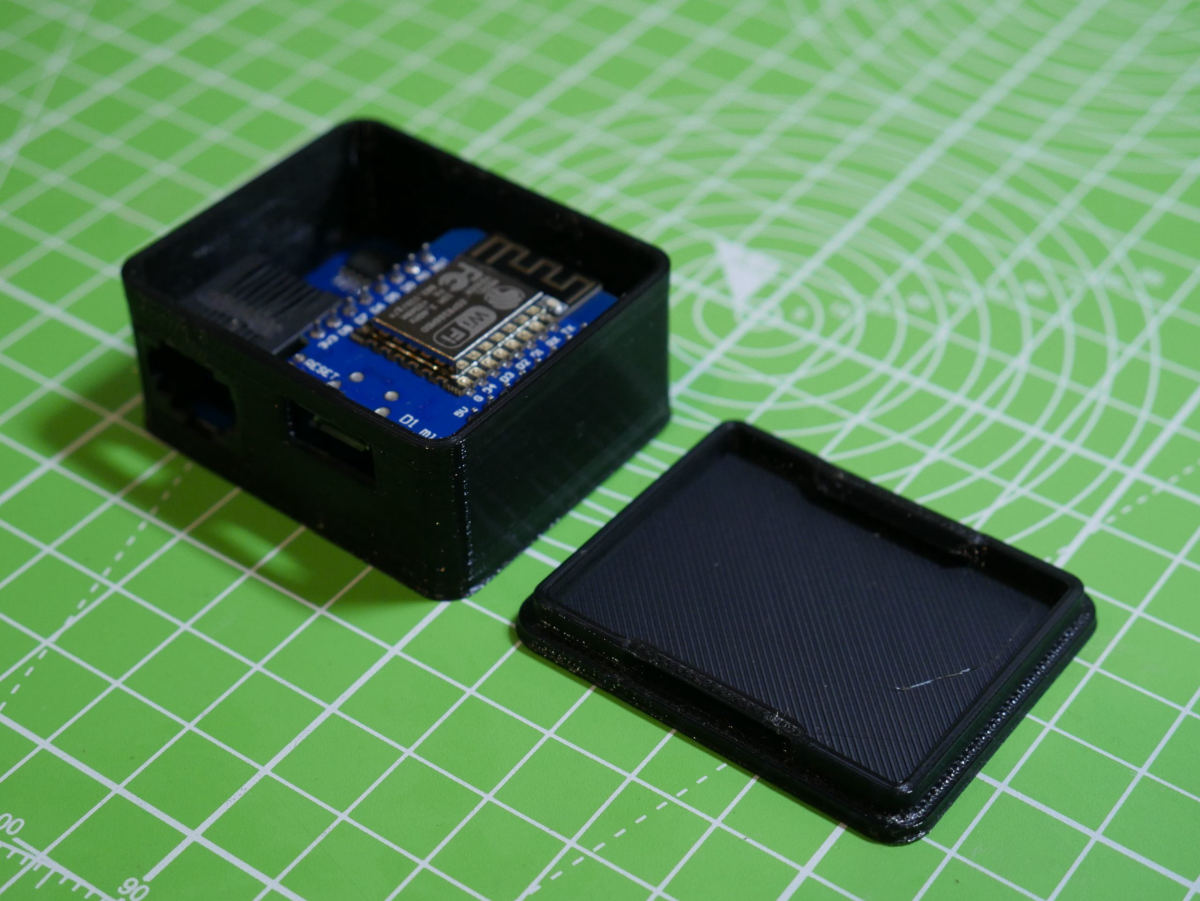
Epever-RS485 Installation and configuration
How to get started with your RS485 to Wifi adaptor
First off thank you for your purchase! the latest version is an evolution of the previous adaptor with a different take with regards to the connectivity and posting data to logging platforms.
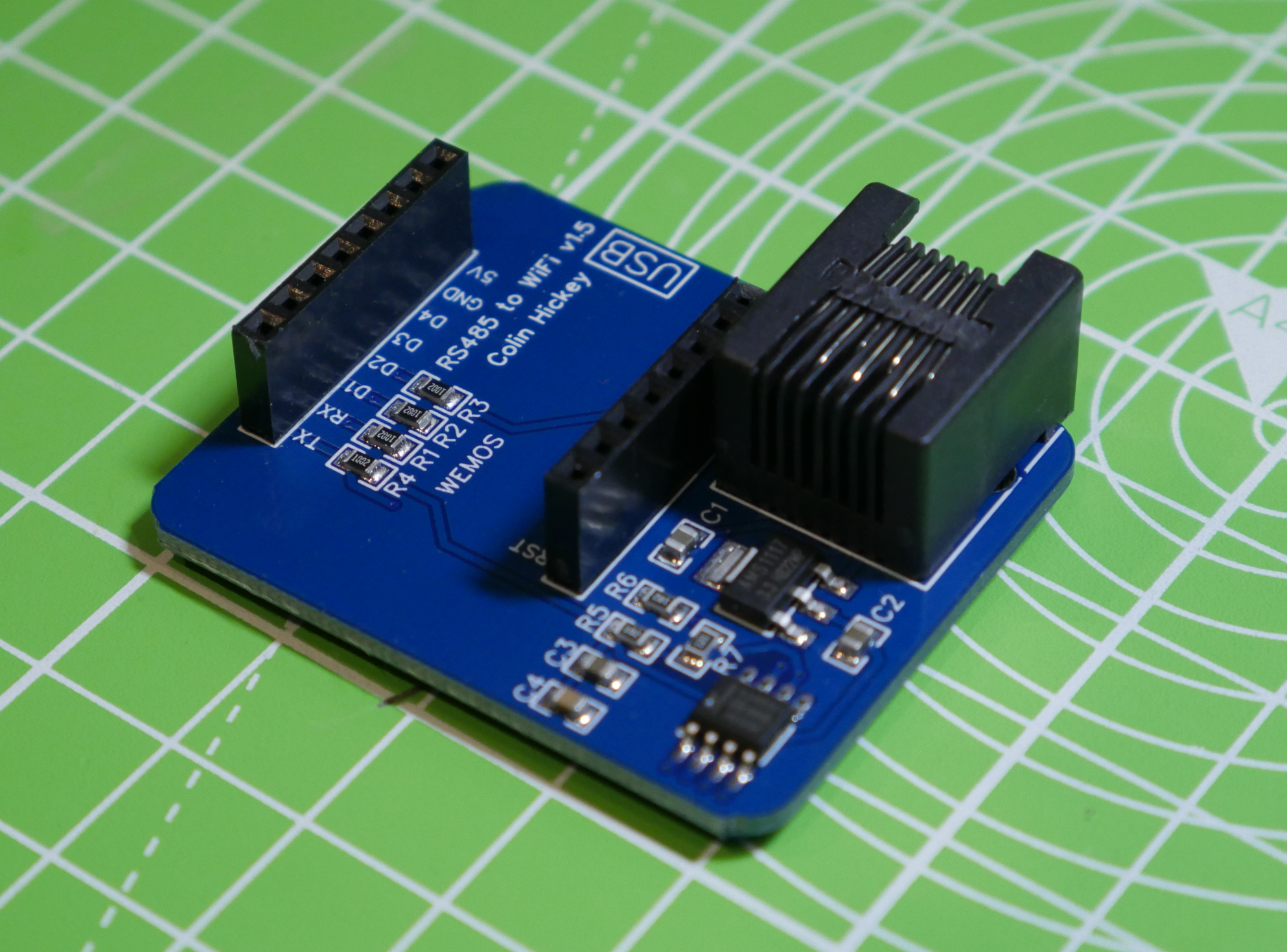
Connecting
You shall need to use a standard RJ45 network cable, make sure it’s not a crossover.
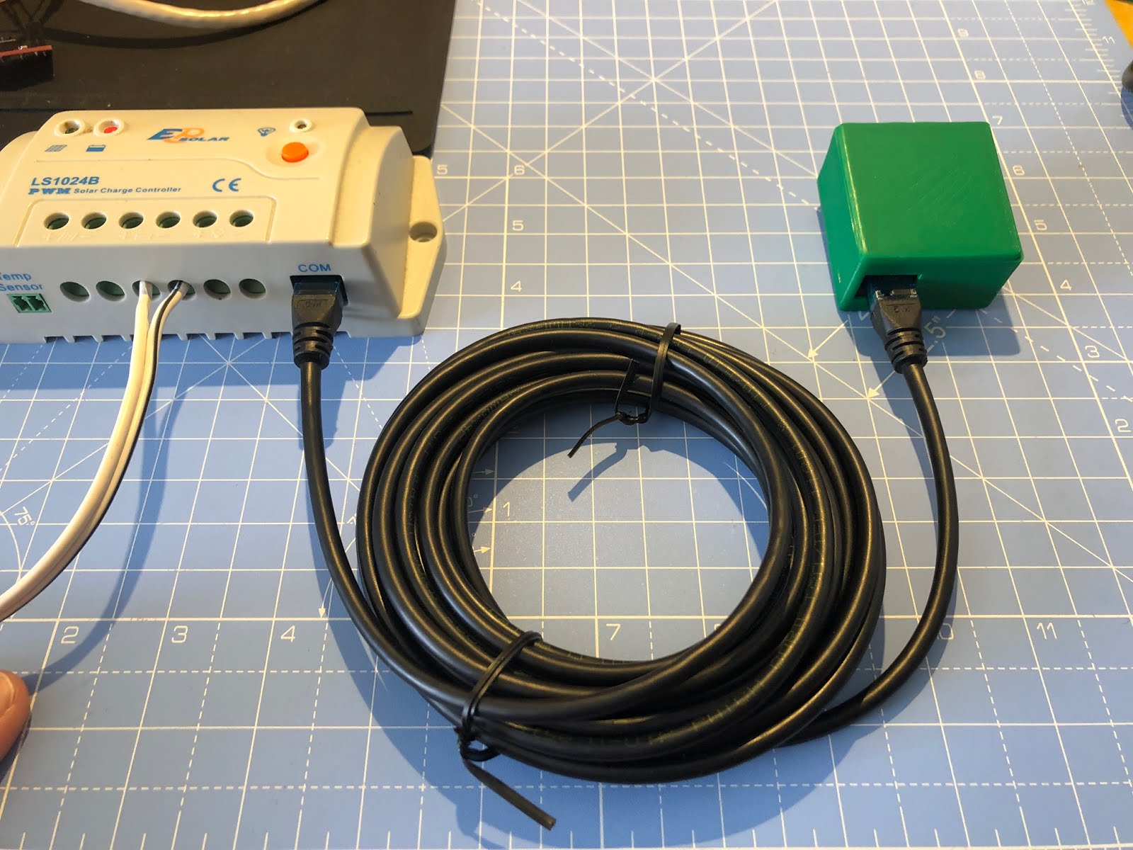
Once it’s connected you shall need to connect and configure your WiFi so the adaptor can connect to your network. I am using my phone and on searching for networks you shall see a new network called RS485-Wifi : –
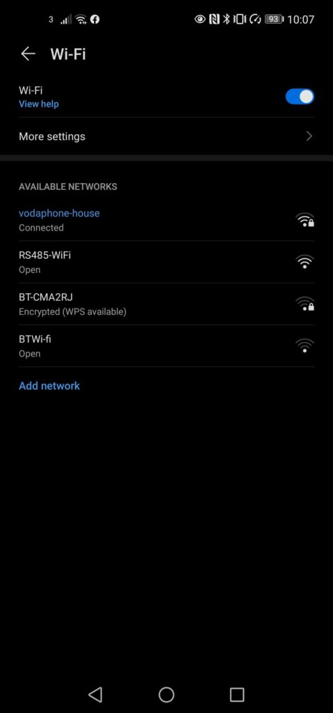
On connecting the next step shall depend on the phone/laptop OS your using to connect. On an android phone it should prompt that the connection needs to be configured and will take you straight to the wifi configuration page. If this does not happen you can go to the confiugration page by opening a browser and manually enter the ip address http:/192.168.4.1 note on most devices you won’t need to enter the http://
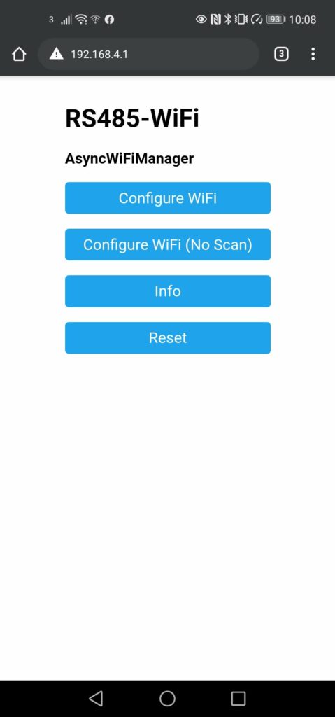
Once connected you shall see the connection screen which details the Wifi configuration manager page. You can select “Configure WiFi” to enter your credentials details.
Here you shall be presented with a list of networks it has found
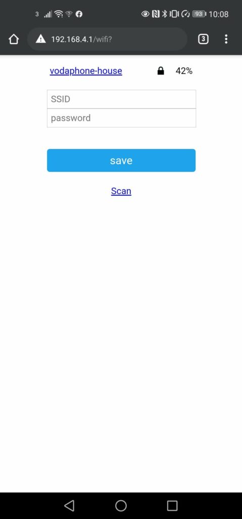
To configure your network you shall need to select your network and then input your WiFi password. The device then shall try connecting to the WiFi network you selected, if it is unable to do so it shall once again go back to the default configuration and you can re-enter your password if you made a tying mistake. Once it is successfully connected you shall need to find the IP address it has selected (this can be found on your home router)
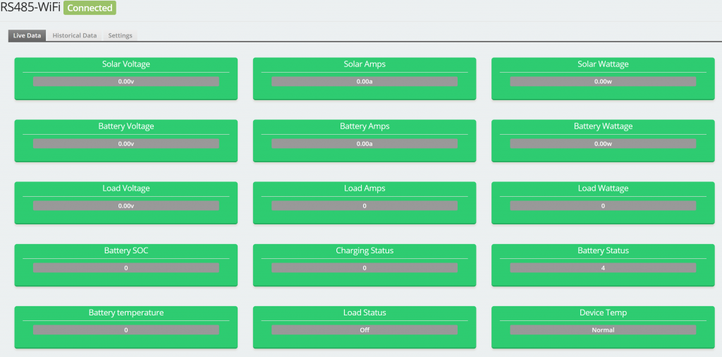
You can then browse to the ip address and shall be presented with the following page showing the current live statistics of the charge controller
If you wish to have the device post the data to either an MQTT server or influxDB server you can do this via the settings tab.
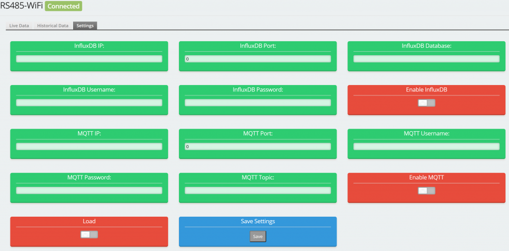
Here you can enter the details and enable the relevant service. The device will post the change controller statistics every 60 seconds.
From here you can also control the load on the device .
Web Flashing
To flash connect the ESP device to your computer using a USB cable
I have hosted the webflashing on a dedicated site which can be accessed at the link below
Once installed it, will create a WiFi access point called “RS485-Wifi”. From there you can follow the Getting Started instructions. If web flashing fails please use the manual flash guide.
NOTE: Make sure to close anything using your devices com port (e.g. Serial monitor)
Powered by ESP Web Tools
INFO
I really recommend using the webflashing method as this is far simpler and you will always get the latest compiled version without a need to install 3rd party applications and also works on any OS.
Manually Compiling
The current version of the custom code is held on github so the latest version is always available.
If you have purchased the RS485-WiFi adaptor with a wemos D1 mini it shall be pre-flashed, if however you are using your own Wemos D1 mini or wish to upgrade to the latest version you shell need to download the latest firmware and flashing tool. You can compile the code yourself to produce the .bin file by loading up the code repository into VS Code or alternatively i provide a compiled binary as part of the github page.
The latest firmware is available here
The flashing tool is available here
The flashing tool is provided by ESP-home team and is a great utility for flashing binary files to ESP devices. Select the version which is appropriate for your Operating System.
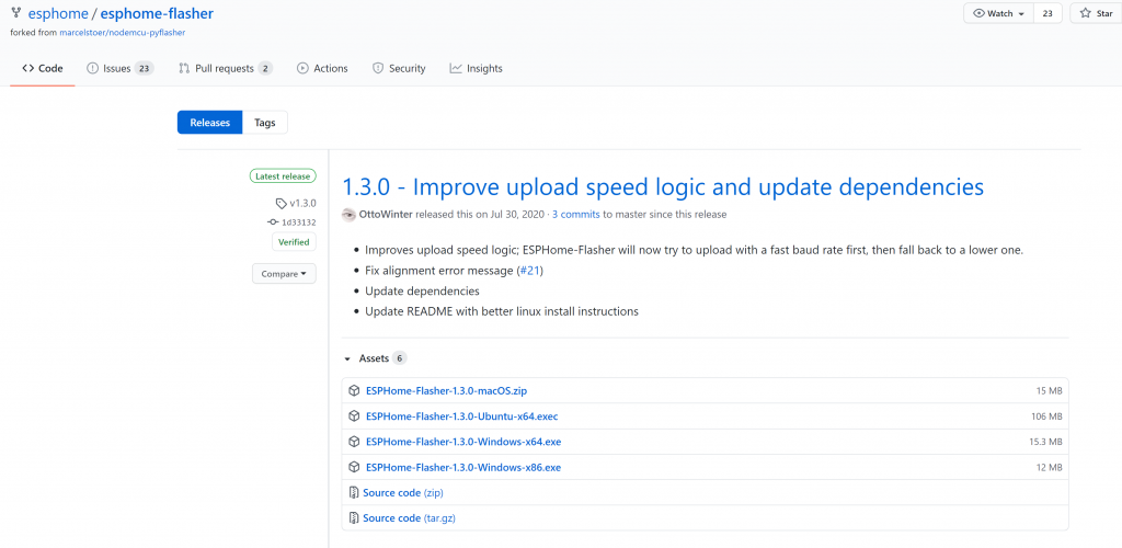
The software does not need to be installed and you just need to launch the program.
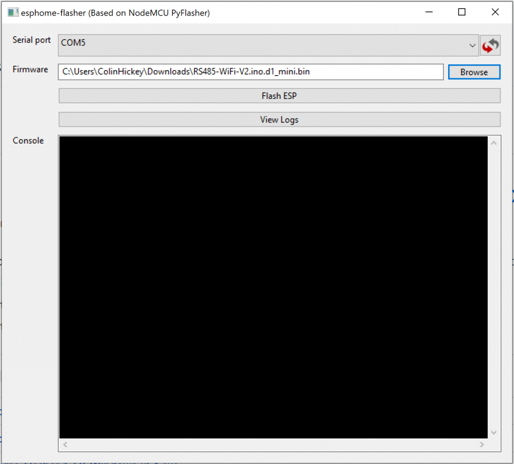
Once launched select the serial port which was created when the Wemos was plugged into your computer and then browse to the update file which you have downloaded. Once the software is configured select “Flash ESP” which shall upload the code to the wemos and output a successful message to the Console window.
Configuration
Using the default software there are many options in the configuration page. In reality however these come down to a just a few items which can be groupe together.
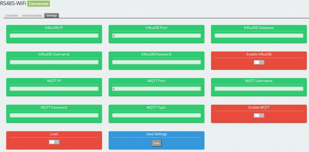
If you wish to push the solar stats to an InfluxDB the following details below must be populated.
- InfluxDB IP:
- InfluxDB Port:
- InfluxDB Database:
- InfluxDB Username:
- InfluxDB Password:
- InfluxDB Toggle Swtich
If you wish to push the solar stats to a MQTT server the following details below must be populated.
- MQTT IP:
- MQTT Port:
- MQTT Database:
- MQTT Username:
- MQTT Password:
- MQTT Toggle Swtich
The final option is to toggle the load which controls the output on the Solar Charge Controller.
Epever ESPHome
Hardware
The current (v1.7) version of the board works natively with ESPHome but if you have an older version of the board then a hardware modification will be required. This is bridging D1 and D2, this needs to be done as DE and RE were originally configured to be used independly but ESPHome can only have one configured flow control pin.
Software
An example yaml configuration file is available at Link
The following is breakdown of the sections of the example configuration files to allow you to create the setup that you require.
Configuration file
modbus:
  flow_control_pin: D1
  id: modbus1
  send_wait_time: 200ms
uart:
  id: mod_bus
  tx_pin: TX
  rx_pin: RX
  baud_rate: 9600
  stop_bits: 1
These two sections tell ESPHOME that we are going to be using modbus for communicating with the Inverter and the pins we shall be using for sending / receiving and also the flow control pin which controls when the device will be sending or receiving data.
modbus_controller:
  - id: solis
    ## the Modbus device addr
    address: 0xA
    modbus_id: modbus1
    setup_priority: -10
    command_throttle: 300ms
    update_interval: 30s
the next important configuration is to define a modbus controller which uses the id which created earlier. One important setting here is the
address: 0x1
this tells esphome what id the inverter is configured for, by default most epever charge controllers use an ID of 1. Please note that the value is in hex so for example the value for 10 would be 0xA. If you have modified your inverter to use something different then you shall need to update the value accordingly.
For reading information you must configure every value you which to read/write. Here we refer to the modbus controller which we have setup in the modbus_controller_id.
sensor:
  - platform: modbus_controller
    modbus_controller_id: solis
    id: inverter_tempterature
    name: "Inverter Temperature"
    address: 33093
    unit_of_measurement: "°C"
    register_type: read
    value_type: U_WORD
    accuracy_decimals: 1
    filters:
      - multiply: 0.1
To breakdown each item
id: inverter_tempterature
This is an ID which you assign to the device which will be used within Home Assistant.
name: "Inverter Temperature"
This is a friendly name which we shall be assigned and used within Home Assistant.
address: 33093
This part is very important as it is the address which ESPHOME will use for reading. This is unique for every item you wish to read and you should be able to find a list of what registers are available for your inverter from Solis.
unit_of_measurement: "°C"
As per the name this defines the unit of measurement be it degree in this example of V for voltage.
register_type: read
This defines if the registers is a read or write type. Typically most registers are read only.
value_type: U_WORD
This defines the length of the data being read, typically this is a UWORD for a single item.
accuracy_decimals: 1
This tells ESPHOME how you wish to present the data, you can have 1 decimal place as in this example or 2 or even 0 for no decimal places and just whole numbers.
    filters:
      - multiply: 0.1
Lastly this defines the multiplying factor. Registers show a larger number than is shown so a multiplying factor must be set so that it returns a valid figure.
Troubleshooting
Hardware
They are designed for my hardware solution which can be found at
https://store.eplop.co.uk/products/epever-rs485
This includes a custom PCB which then uses a Wemos D1 mini board and then combined with a custom made cable which allows the board to get both the data from the inverter but also be powered from the inverter itself so no external power is required.
- If you are attempting to get this working with a self made solution you will need to check that you have created your solution in a similar way to the way my board functions such as pins used etc.
- When first plugged in the wemos board will flash it's LED once which will let you know that you are successfully getting power across the custome cable.
- You must ensure that you use a regular network cable and not a crossover cable.
Software
One of the most common issues is the ID of the device being different. The ID is a unique identifyer which allows you to have several inverters connected and monitored. Because of this the ID which you have set on your inverter must match the setting in your yaml file. Typically 1 is used for epever inverters but it may have been changed by your installed. The number is hex so in the example below it is set to "1" and if you wanted to set ID 10 then it would be "address: 0xA"
modbus_controller:
  - id: epever
    ## the Modbus device addr
    address: 0xA
    modbus_id: modbus1
    setup_priority: -10
    command_throttle: 300ms
    update_interval: 30s