
Solis-RS485 Installation and configuration
Getting Started
Hardware
The configurations shown are designed for my hardware solution which can be found at
https://store.eplop.co.uk/products/solis-rs485-to-wifi-adaptor
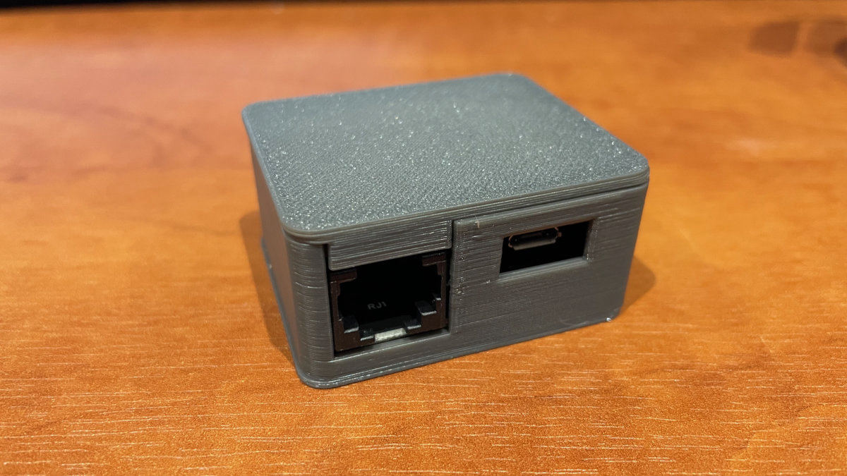
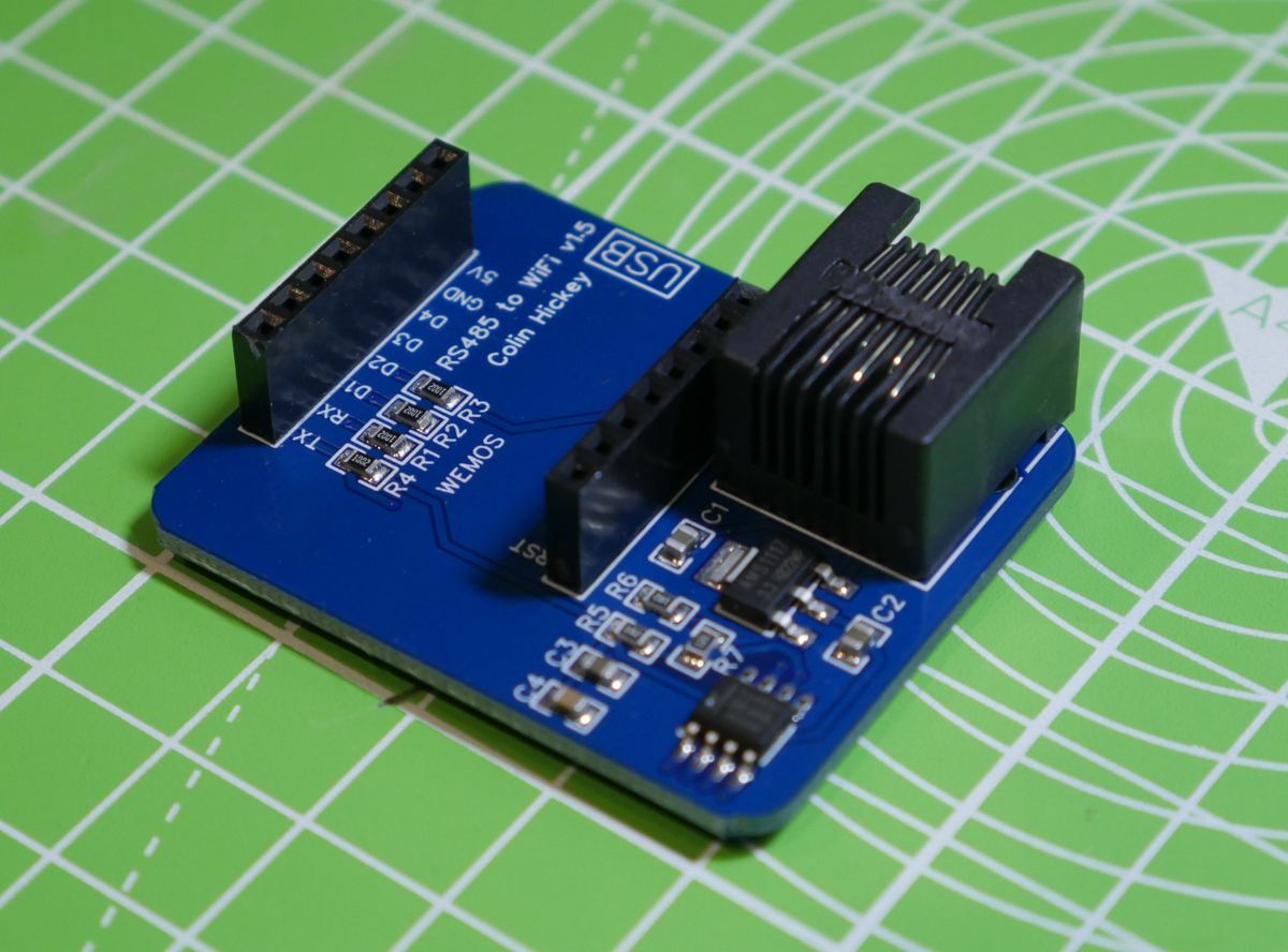
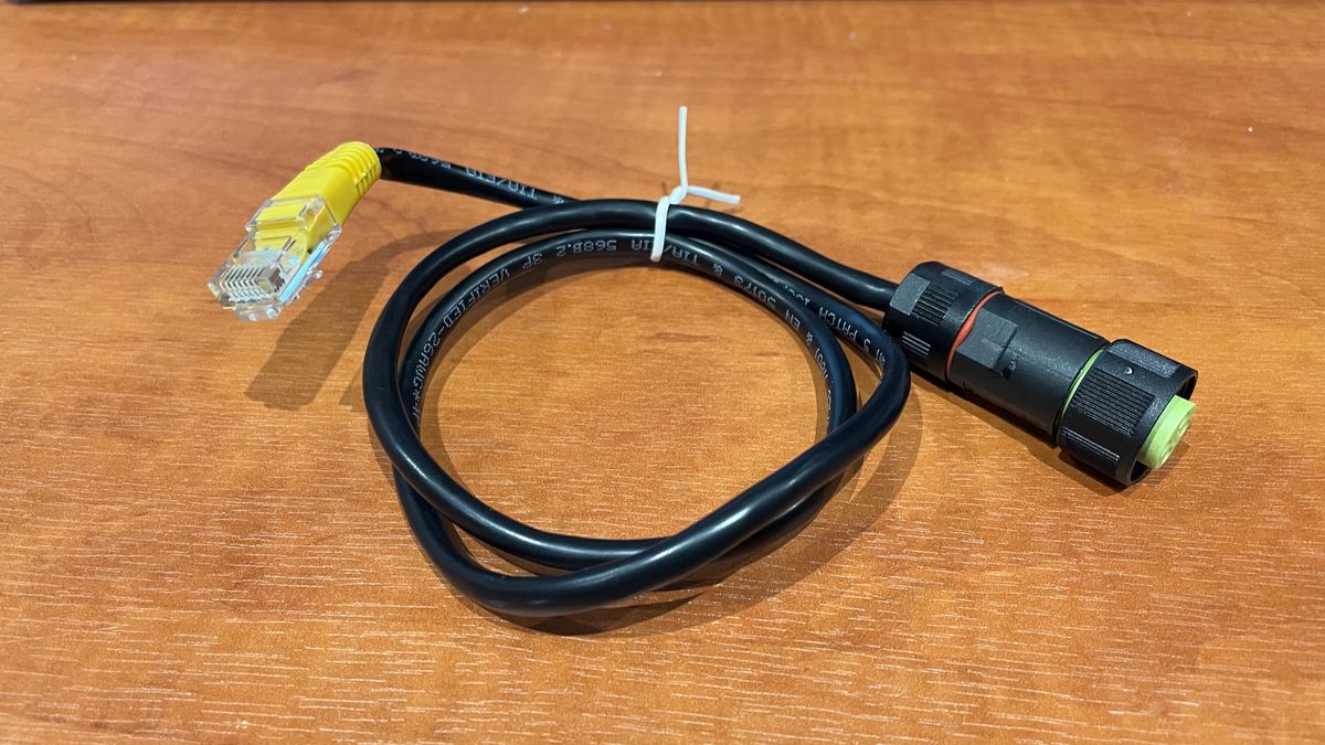
This includes a custom PCB which then uses a Wemos D1 mini board and then combined with a custom made cable which allows the board to get both the data from the inverter but also be powered from the inverter itself so no external power is required.
Software
Esphome is used as the sotware choice which integrates seamlessly with Home Assistant. the configuration is held in yaml files which can then be easily modifed as necessary. I have provided a breakdown of the yaml configuration here Solis ESPHOME
Examples
The files here are provided as examples but even if they are not for your exact model they should still work so long as the physical connections are the same and it's a case of reading different registers.
Solis ESPHome
Hardware
They are designed for my hardware solution which can be found at
https://store.eplop.co.uk/products/solis-rs485-to-wifi-adaptor
This includes a custom PCB which then uses a Wemos D1 mini board and then combined with a custom made cable which allows the board to get both the data from the inverter but also be powered from the inverter itself so no external power is required.
Software
The following is breakdown of the sections of the example configuration files to allow you to create the setup that you require.
Configuration file
modbus:
  flow_control_pin: D1
  id: modbus1
  send_wait_time: 200ms
uart:
  id: mod_bus
  tx_pin: TX
  rx_pin: RX
  baud_rate: 9600
  stop_bits: 1
These two sections tell ESPHOME that we are going to be using modbus for communicating with the Inverter and the pins we shall be using for sending / receiving and also the flow control pin which controls when the device will be sending or receiving data.
modbus_controller:
  - id: solis
    ## the Modbus device addr
    address: 0xA
    modbus_id: modbus1
    setup_priority: -10
    command_throttle: 300ms
    update_interval: 30s
the next important configuration is to define a modbus controller which uses the id which created earlier. One important setting here is the
address: 0x1
this tells esphome what id the inverter is configured for, by default most solis inverters use an ID of 10. The value here is 0xA which is 10. If you have modified your inverter to use something different then you shall need to update the value accordingly.
For reading information you must configure every value you which to read/write. Here we refer to the modbus controller which we have setup in the modbus_controller_id.
sensor:
  - platform: modbus_controller
    modbus_controller_id: solis
    id: inverter_tempterature
    name: "Inverter Temperature"
    address: 33093
    unit_of_measurement: "°C"
    register_type: read
    value_type: U_WORD
    accuracy_decimals: 1
    filters:
      - multiply: 0.1
To breakdown each item
id: inverter_tempterature
This is an ID which you assign to the device which will be used within Home Assistant.
name: "Inverter Temperature"
This is a friendly name which we shall be assigned and used within Home Assistant.
address: 33093
This part is very important as it is the address which ESPHOME will use for reading. This is unique for every item you wish to read and you should be able to find a list of what registers are available for your inverter from Solis.
unit_of_measurement: "°C"
As per the name this defines the unit of measurement be it degree in this example of V for voltage.
register_type: read
This defines if the registers is a read or write type. Typically most registers are read only.
value_type: U_WORD
This defines the length of the data being read, typically this is a UWORD for a single item.
accuracy_decimals: 1
This tells ESPHOME how you wish to present the data, you can have 1 decimal place as in this example or 2 or even 0 for no decimal places and just whole numbers.
    filters:
      - multiply: 0.1
Lastly this defines the multiplying factor. Registers show a larger number than is shown so a multiplying factor must be set so that it returns a valid figure.
Troubleshooting
Hardware
They are designed for my hardware solution which can be found at
https://store.eplop.co.uk/products/solis-rs485-to-wifi-adaptor
This includes a custom PCB which then uses a Wemos D1 mini board and then combined with a custom made cable which allows the board to get both the data from the inverter but also be powered from the inverter itself so no external power is required.
- If you are attempting to get this working with a self made solution you will need to check that you have created your solution in a similar way to the way my board functions such as pins used etc.
- When first plugged in the wemos board will flash it's LED once which will let you know that you are successfully getting power across the custome cable.
- You must ensure that you do not twist the cable separate from the plug as you can easiliy snap off the soldered connections.
Software
One of the most common issues is the ID of the device being different. The ID is a unique identifyer which allows you to have several inverters connected and monitored. Because of this the ID which you have set on your inverter must match the setting in your yaml file. Typically 10 is used for Solis inverters but it may have been changed by your installed. The number is hex so in the example below it is set to "A" and if you wanted to set ID 1 then it would be "address: 0x1"
modbus_controller:
  - id: solis
    ## the Modbus device addr
    address: 0xA
    modbus_id: modbus1
    setup_priority: -10
    command_throttle: 300ms
    update_interval: 30s